


Geogrid Retaining Wall Installation
Below is a step by step Geogrid Retaining Wall Installation process. This is to be used as a guide and instruction manual of the proper procedures needed to install a MagnumStone project correctly and efficiently. All information provided is to be used at the discretion of the user.
- MagnumStone is available in 0 / 2.4 / 4.5 degree batter (setback) Check with your local producer for availability.
- Face textures vary from producer to producer. Please check with your local sales representative for more information and styles available.
- It is always recommended that a qualified engineering consultant be hired for all projects by the owner of the gravity retaining wall project.
- Soils test and analysis should be performed before design and excavation are performed. Understanding and utilising the correct soils information will help to determine the length depth of excavation and gravity retaining wall pieces.
Call before you dig. These are typically free services in most counties and jurisdictions. They will come to the site and mark out where all of the utilities are underground.
Canada – digsafe.ca
USA – call811.com
Australia – byda.com.au
United Kingdom – national-one-call.co.uk
New Zealand – beforeudig.co.nz
STEP
01
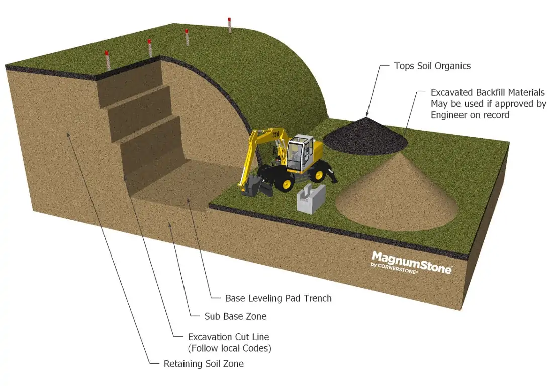
Planning The Geogrid Retaining Wall
Review
-
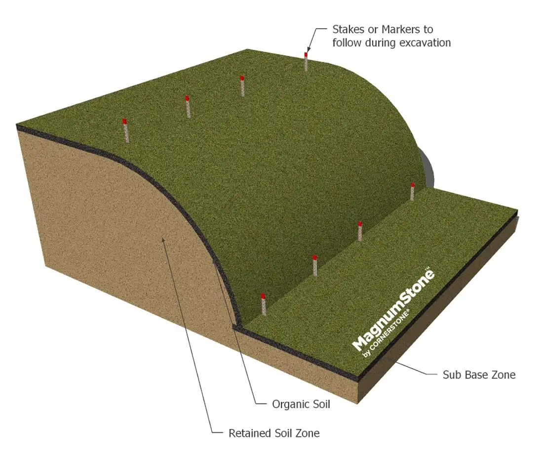
Mark the bottom and top of the geogrid retaining wall excavation location with spray paint or stakes
-
Establish proper elevation points for both the bottom and top of the wall before starting excavation
-
Organic Materials should not be used in any Backfill Zones
-
Store and protect good quality Backfill Materials from inclement weather during construction
STEP
02
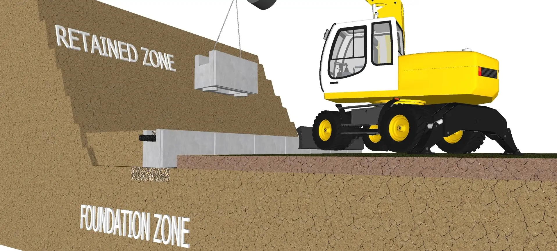
Excavating The Geogrid Retaining Wall
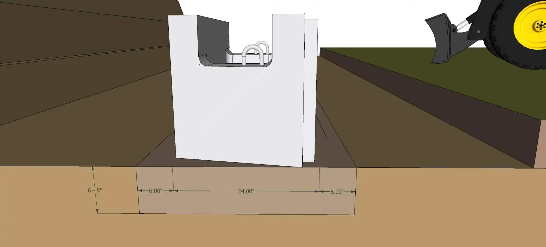
Figure #1
Review
-
Excavate and prepare Sub Base Levelling Trench 6 to 8″ (150 to 200mm) below first course. This will be filled with a good 3/4″ (20mm) road base material.
-
Figure 1 – The Leveling Pad Trench Depth should be cut out to approximately 6″ (15cm) from the back and and the front of the total depth of the base course. For instance, MagnumStone Standard Unit 24″ + 6″(front) + 6″(back) = 36″ total (610 mm + 150 mm + 150 mm = 910 mm)
-
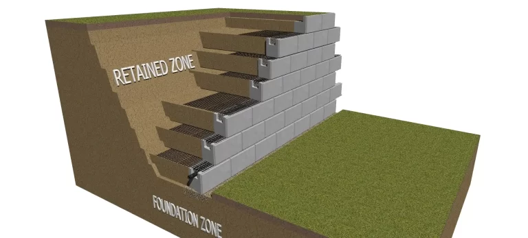
Typical retaining wall burial depth or embedment Depth is 6″ to 12″ (150 to 300mm) Or 10% of the total height of the wall. Follow engineers cross section details or design parameters to ensure the correct embedment depth is being followed.
-
Excavate cut line to a 2 to 1 slope or greater. Check with local codes and regulations to ensure they are being followed correctly.
STEP
03
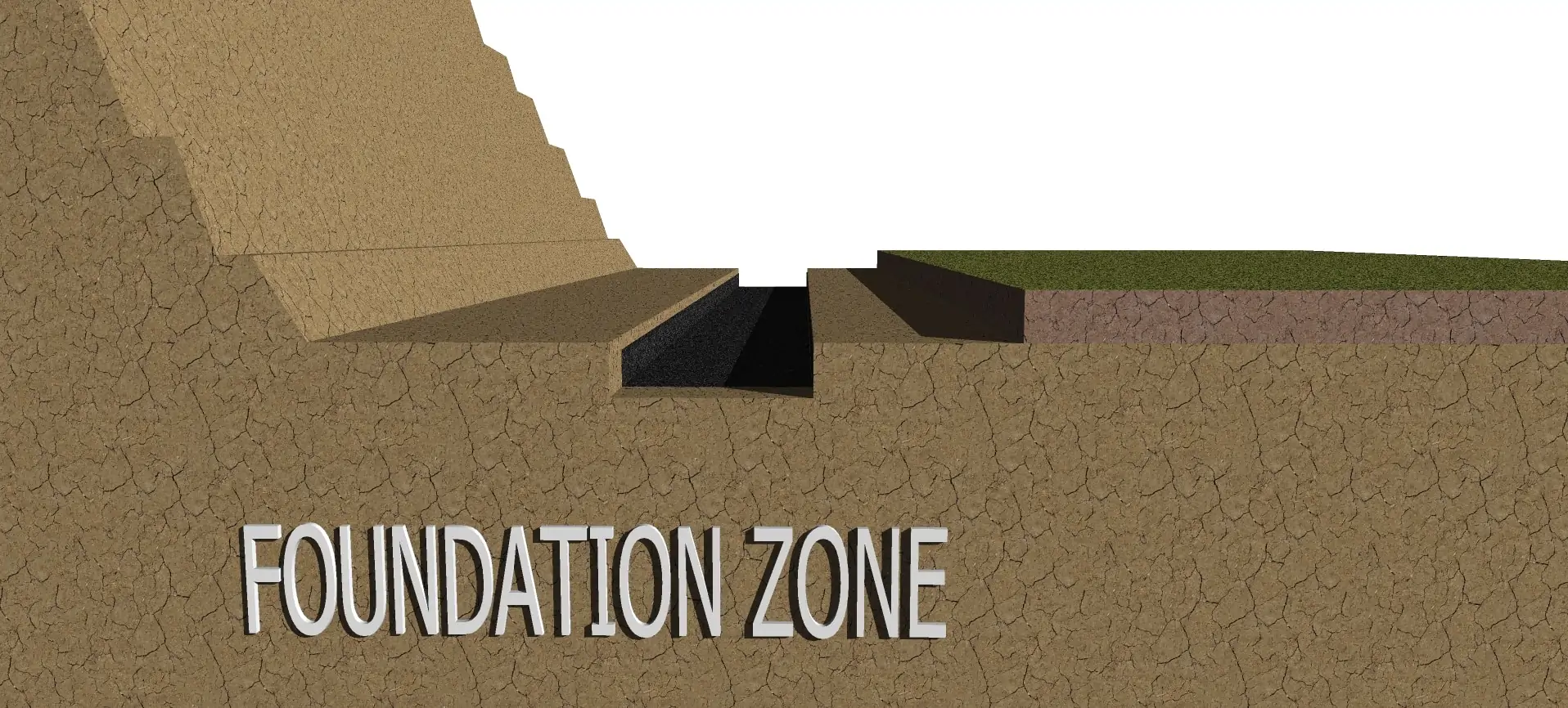
Sub Base and Base Stabilization Fabrics
Review
-
Compact Sub Base to 95% Standard Proctor Density or greater
-
Remove any Organic or poor soils in the Sub Base and replace with proper reinforced fill materials before compacting
-
(Optional) place 5′ to 6′ (127 to 152mm) wide Base Stabilization Fabric on top of levelling pad trench
-
Base Stabilization Fabrics will help prevent sub base materials from mixing with the gravel base leveling pad during compaction
-
Fabric also provides extra Structural Bearing Stability to the base leveling pad
STEP
04
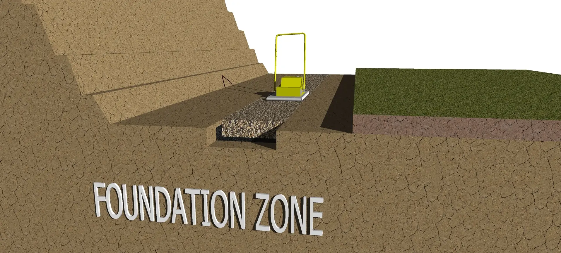
Compact Gravel Leveling Pad
Review
-
Typically a 3/4″ (20mm) road crush gravel or equivalent is used for the base leveling pad
-
Compact Gravel Leveling Pad to 95% Standard Proctor Density or greater
-
Correct Moisture Content in the gravel will help in reaching proper compaction
-
It is crucial that the base is level front to back and side to side. Any imperfections will be exaggerated as the wall goes taller
STEP
05
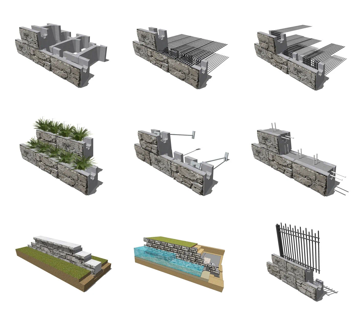
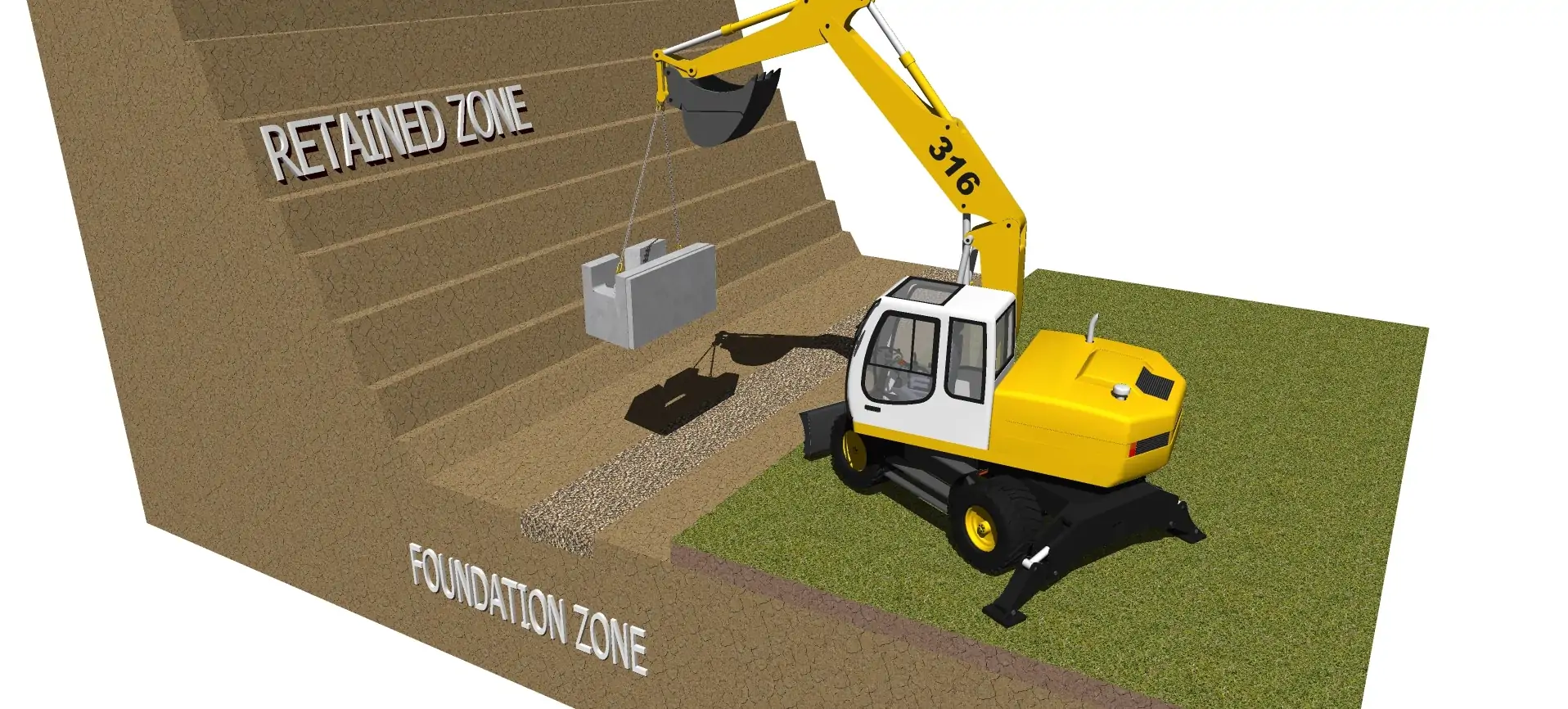
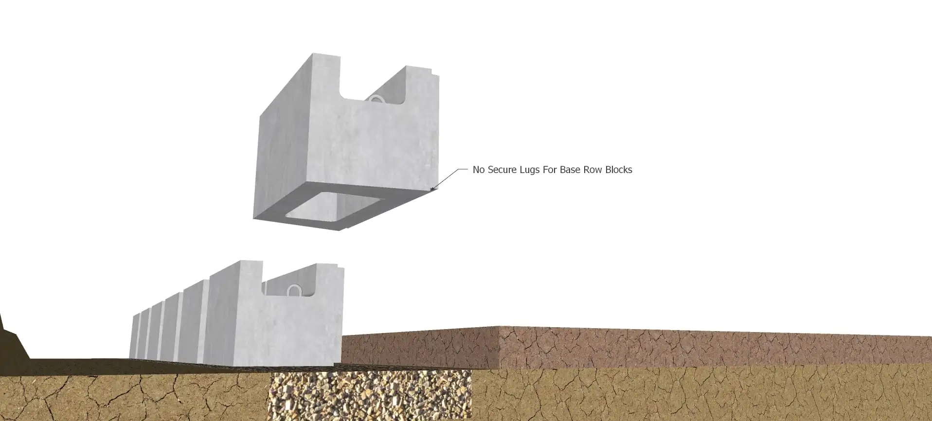
Laying First Course of MagnumStone Retaining Wall Blocks
Review
-
Place a steel stake at either end of the leveling pad to establish the back of the first course of units
-
Secure a tight string line to the stakes at either end which will provide the guide to line up the back of each MagnumStone™ base block
-
The distance of the string line between the steel stakes may vary due to heavy winds
-
MagnumStone™ base blocks, placed on the leveling pad, are manufactured without SecureLugs
-
Place each unit on top of the leveling pad in such a way as not to disturb the level gravel
STEP
06
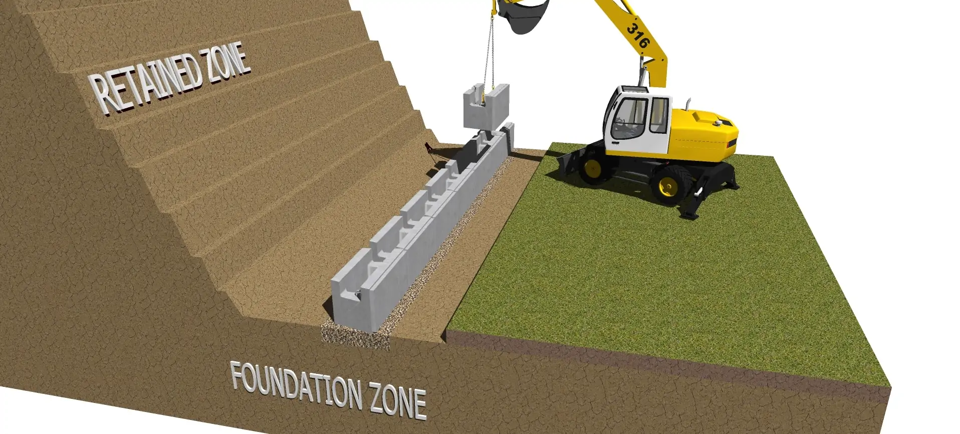
Complete Base Row Installation
Review
-
Complete the first course of the MagnumStone geogrid retaining wall blocks
STEP
07
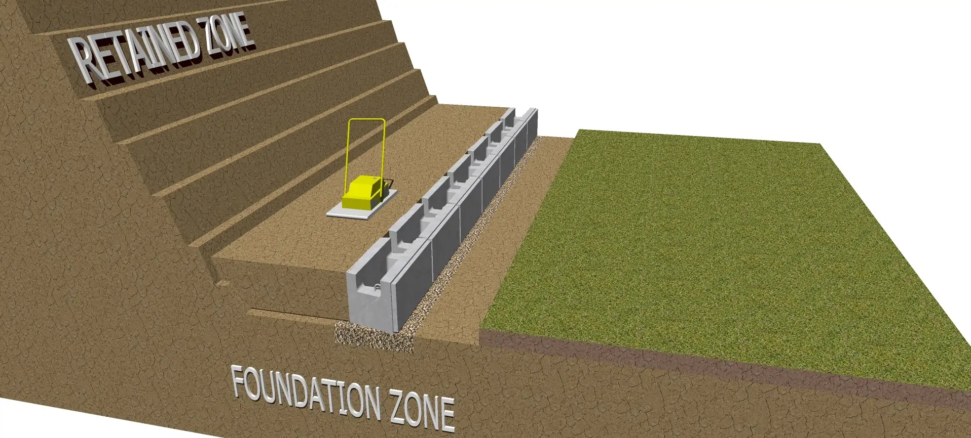
Backfill the Gravity Retaining Wall
Review
-
Backfill the MagnumStone blocks with an approved material. Run a plate vibratory compactor (for smaller lifts) or a roller / vibrating compactor over backfill materials with the proper moisture content.
-
Backfill in lifts or layers that are acceptable to the soils conditions and size of the compaction equipment.
-
Proper compaction is crucial to the success of the finished product.
STEP
08
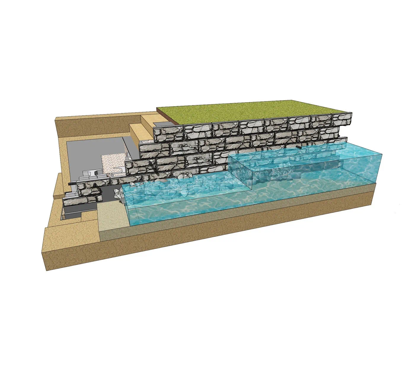
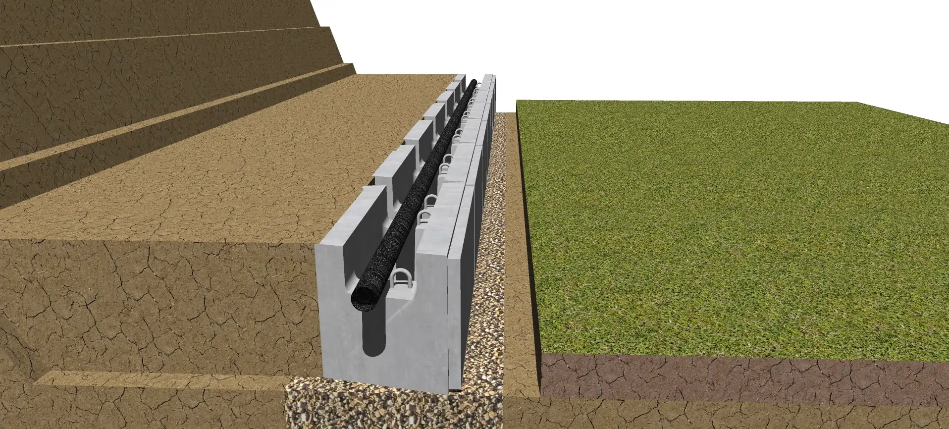
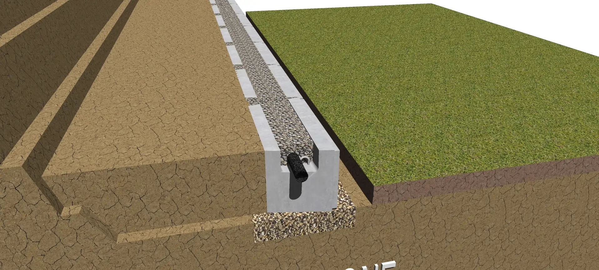
Drain Pipe for Geogrid Retaining Wall
Review
-
Drain Pipe should have adequate slope to drain water in the right direction towards each Drain Pipe Outlet
-
Drain Pipe Outlet can be every 30 or 50 feet (9 or 15 meters)
-
Perforated Drain Pipe, laid in the Horizontal Cores, can be a Sock Wrapped system to help prevent fines from migrating into the pipe
STEP
09
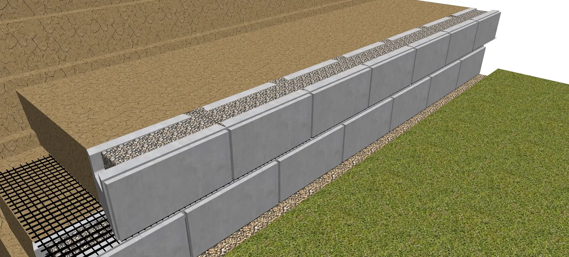
Installing Drain Gravel
Review
-
Clear Crush Drain Gravel is placed in the vertical and horizontal hollow cores after placing and compaction of the backfill materials
-
The Clear Crush Drain Gravel should be 2″ (50mm) below the top of units to allow for SecureLug connection
-
Clear Crush Drain Gravel does not need to be compacted
-
Sweep the top of the MagnumStone™ Blocks clean of all rock and dirt before placing second course of MagnumStone™ Blocks
-
Make sure the Backfill Materials directly behind the wall are placed flush to the top of the units
-
Make sure the Backfill Materials are well compacted and level as possible
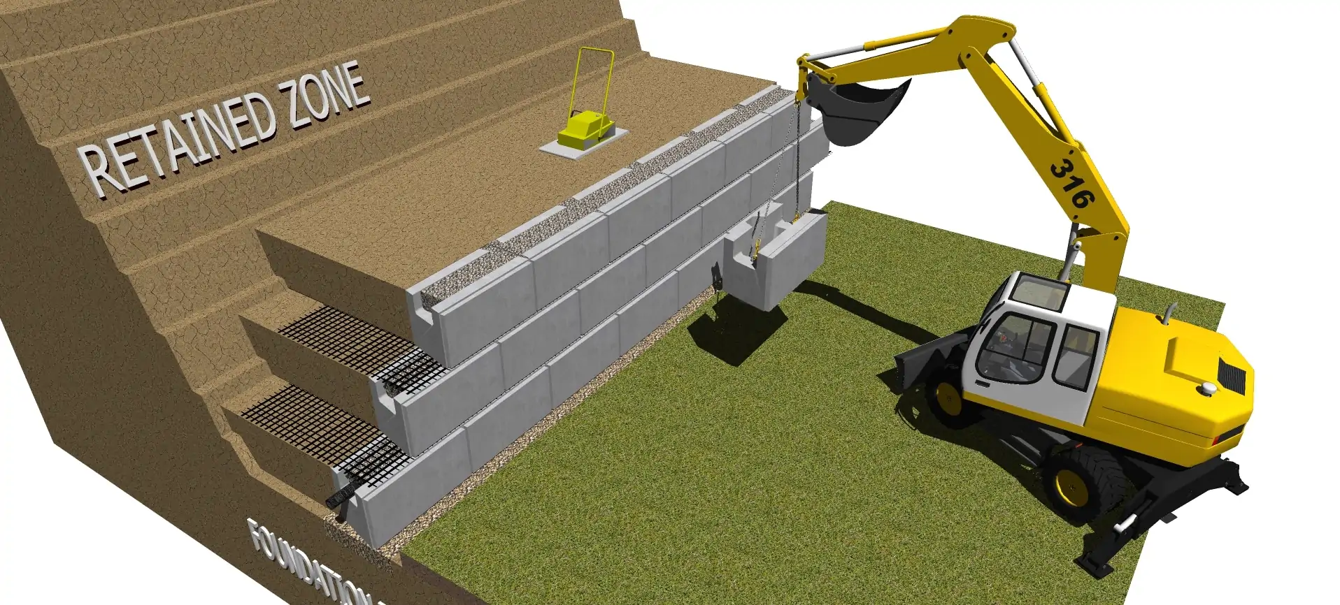
STEP
10
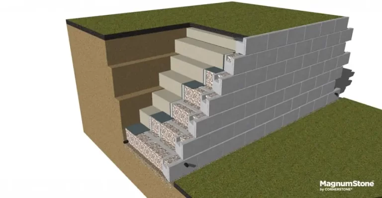
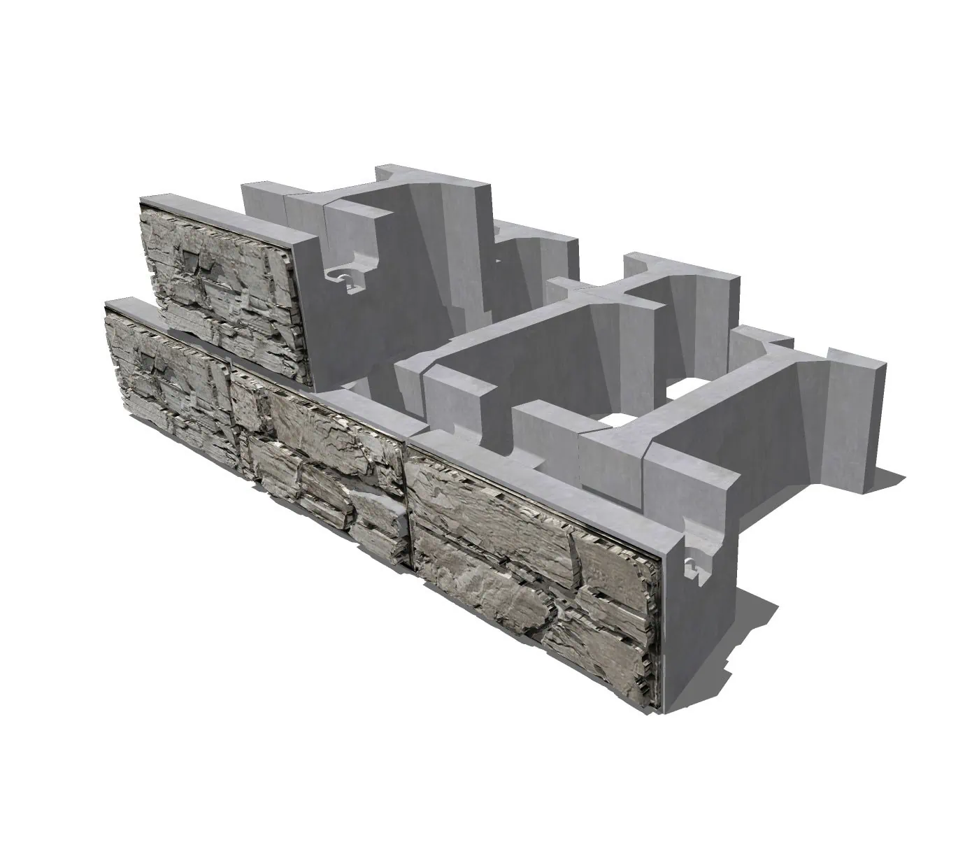
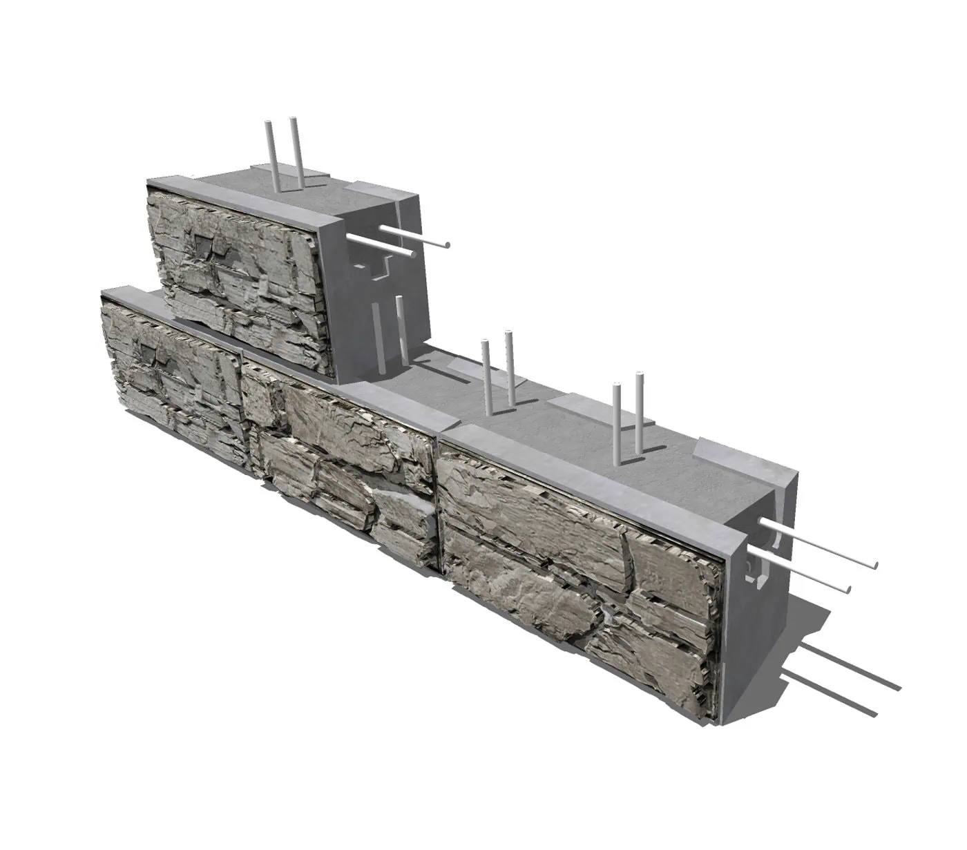
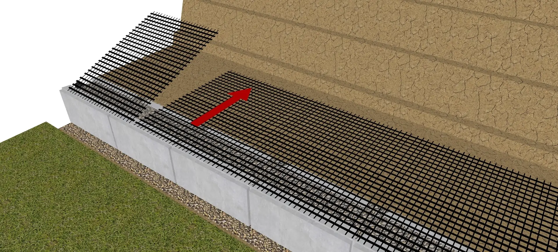
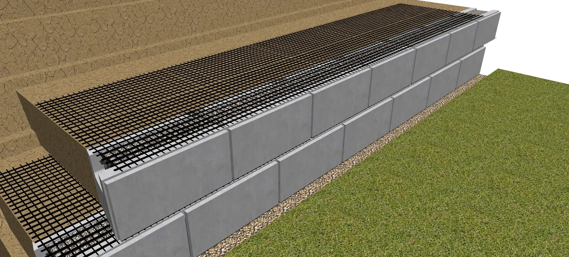
Installing Geogrids to Retaining Walls
Review
-
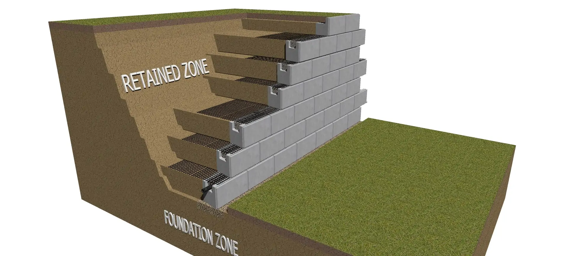
Cut Geogrid Reinforcement to the length specified in the design. Each project has specific cross sections with lengths of geogrid shown.
-
Geogrids are manufactured in two directions Uni-axial or Bi-axial. Uni-axial grid has one direction of strength and that direction needs to be oriented perpendicularly to the face of the wall during installation. Bi-axial grid can be laid in two directions, perpendicular and lengthwise to the face of wall (ensure that the lengthwise direction is still in accordance to the length specified by the Engineer’s design)
-
Correct geogrid orientation, strength and length is crucial to the success of the wall project
-
Each Geogrid length should be laid parallel and adjacent to each other but never overlapping
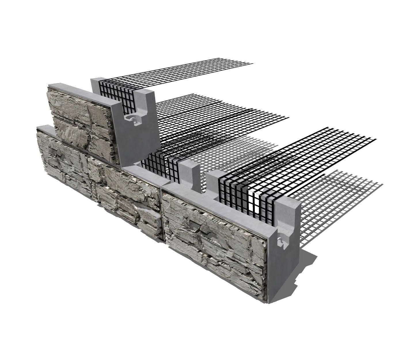
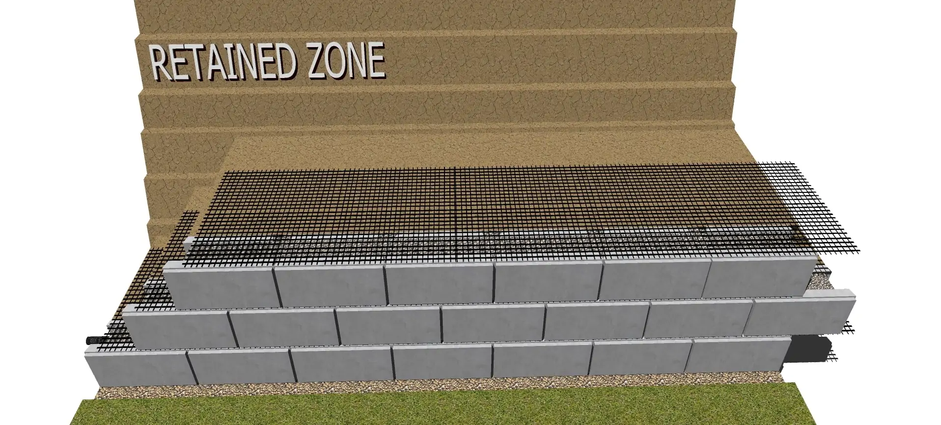
STEP
11
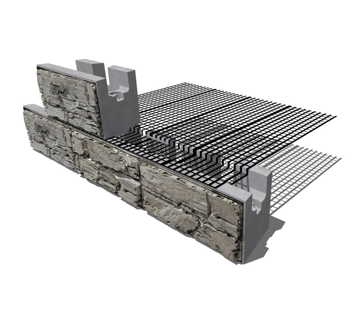
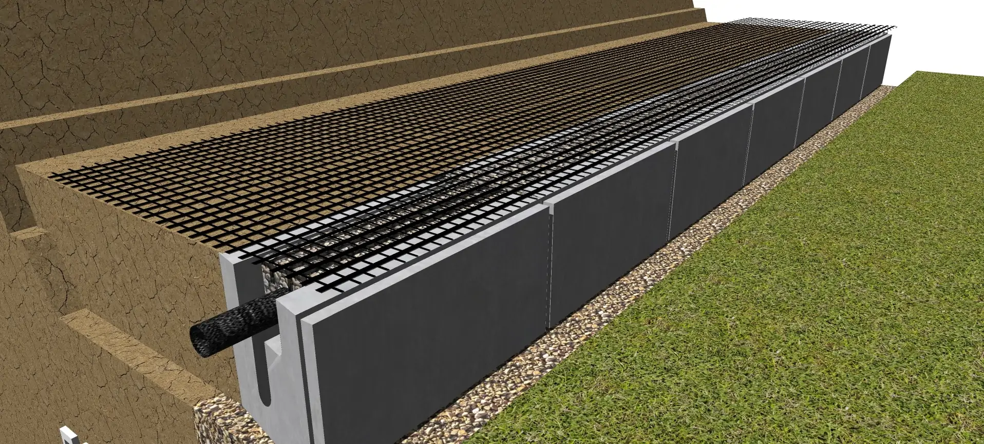
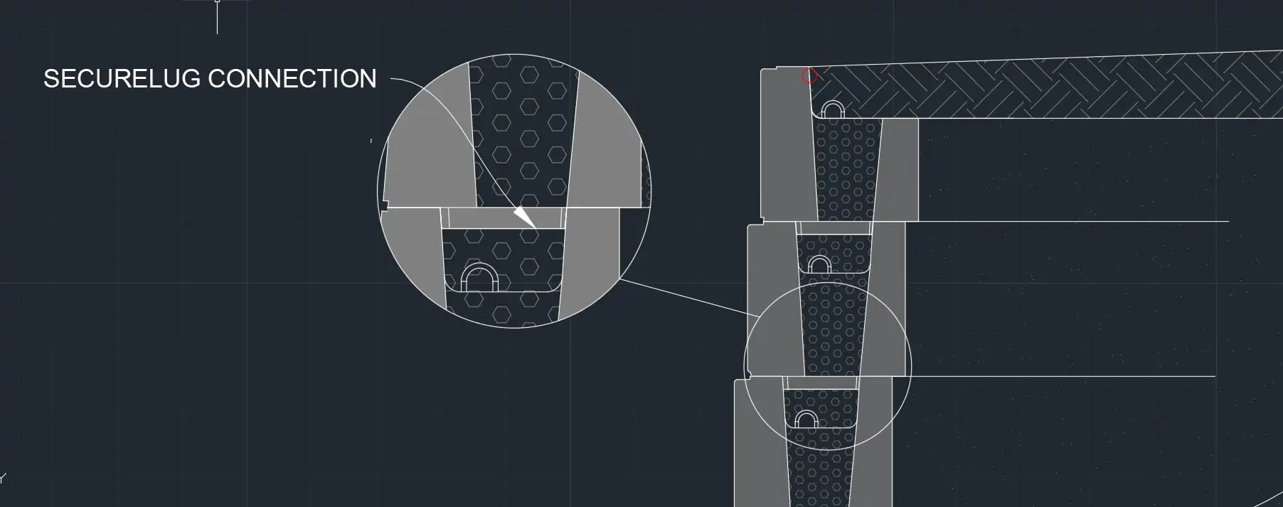
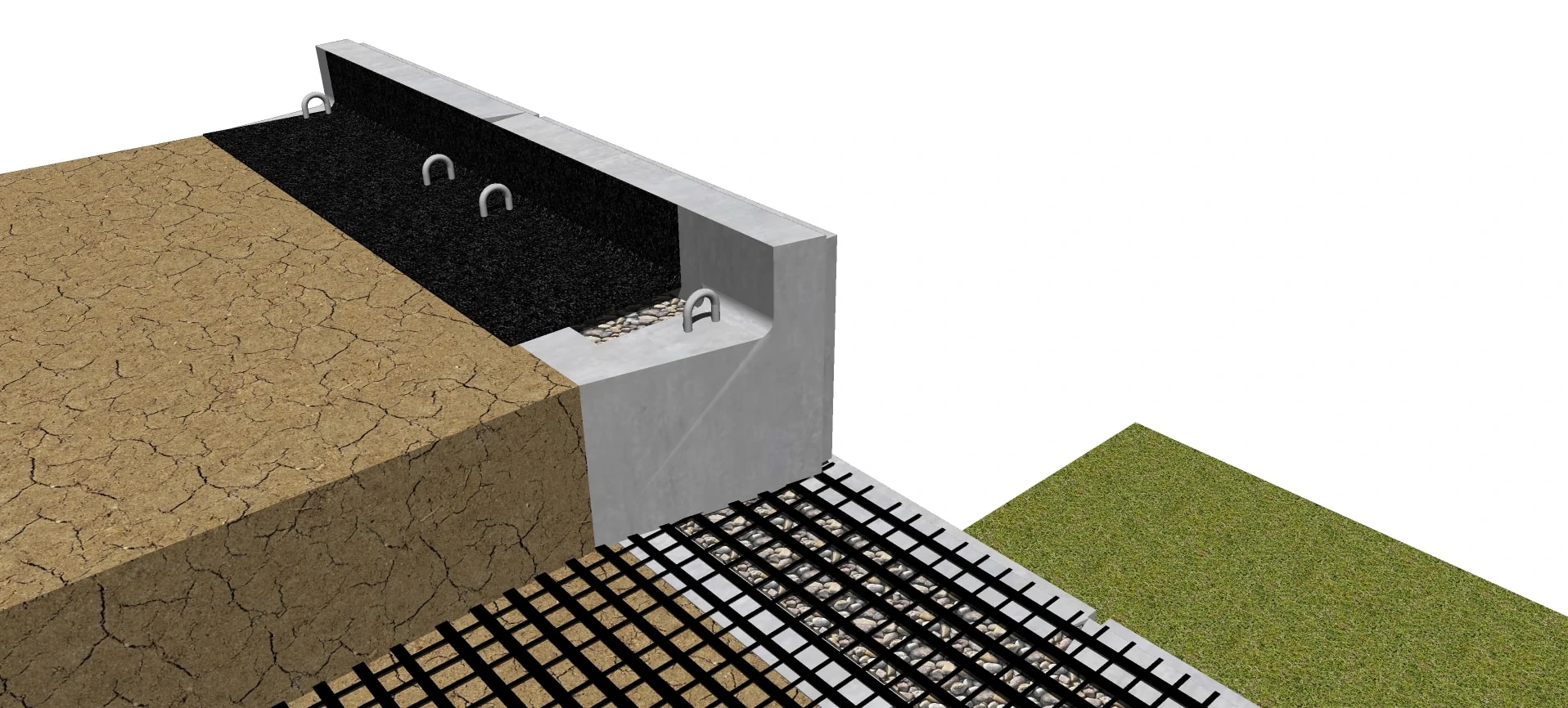
Geogrid and Connection with Second Layer
Review
-
Place the Geogrid as far forward on the MagnumStone™ units as possible without revealing it on the face
-
Place the next course of MagnumStone™ units on top of the lower units and Geogrid at a half bond to the lower units
-
The two SecureLugs will fit securely into the hollow cores of the two units below and lock the Geogrid into the gravel core
-
The gravel in the lower units will be recessed 2″ (50mm) or more to allow for the SecureLugs connection
-
Complete the installation of units on the Geogrid Reinforced courses
-
Make sure each unit is installed against the unit next to it leaving no gaps between unit joints
-
Use stakes or backfill materials to maintain the tension of the Geogrid during backfilling
-
Do not drive equipment directly on top of Geogrid
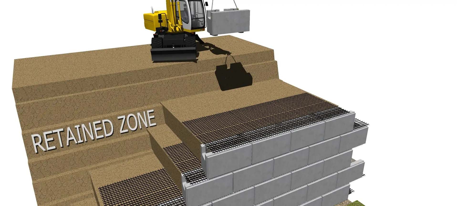
STEP
12
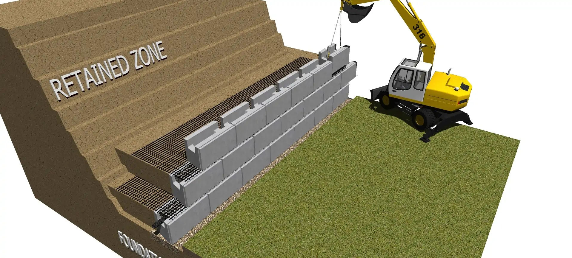
Backfill Reinforced Geogrid Layers

Review
-
Backfill the Reinforced Zone by placing materials from the back of the wall towards the end of the Geogrid
-
Install drainage gravel in the cores after placing and compacting backfill materials
-
Install and compact backfill materials in Lifts no greater than 8″ (203mm). Check with the compaction equipment for maximum lift details.
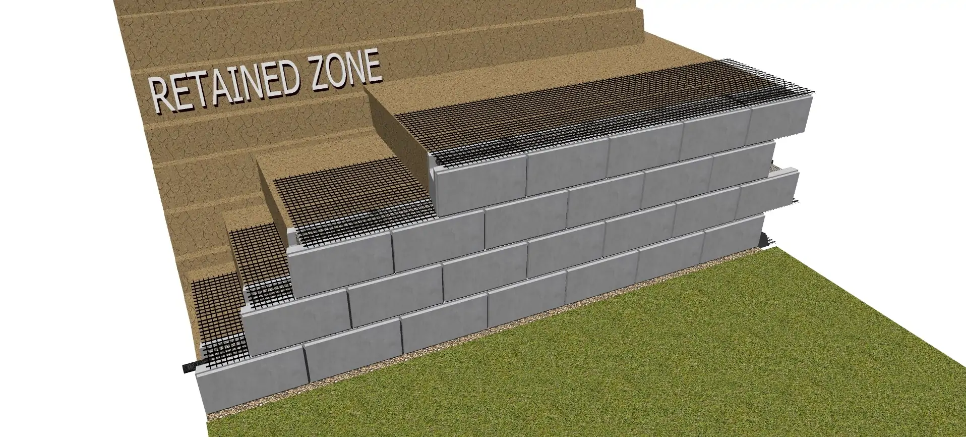
STEP
13
Backfill & Building your Geogrid Retaining Wall
Review
-
Install third row of blocks following the same guidelines as previous steps.
STEP
14
Backfill & Building your Geogrid Retaining Wall
Review
-
Install fourth row of MagnumStone Retaining Wall blocks following the same guidelines as previous steps.
STEP
15
Backfill & Building your Geogrid Retaining Wall
Review
-
Install third row of blocks following the same guidelines as previous steps.
STEP
16
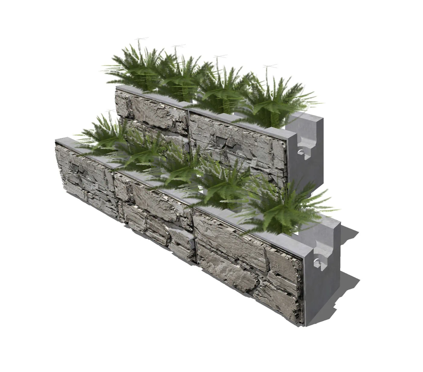
Top of Wall Units

Review
-
Complete the top of the wall with MagnumStone™ Top Units
-
MagnumStone™ Top Units are manufactured with the back panel 8″ lower than the front face panel
-
The Clear Crush Drain Gravel and backfill materials will be placed flush to the top of lowered back panel. There are times when more than 8″ (203mm) of top soils may be required.
STEP
17
Soil Separating Filter Fabrics
Review
-
Place a 6 ft (1.8m) wide Soil Separating Filter Fabric on top of the backfill and drainage gravel and against the back of the last units before placing the planting soils
-
The fabric will prevent planting soil fines from staining the face of the wall and migrating into the Clear Crush Drain Gravel (Angular Aggregate free of fines)
STEP
18
Final Grading of Geogrid Retaining Wall Installation
Review
-
Insure that final grading is done on top and bottom of the retaining wall
-
Make sure to protect newly placed planting soil from erosion during heavy rains or surface runoff